You might think you can wait until later to learn about turn coordinators and how to use them. After all, you just want to get up in the air, right? Not so fast. Patience young grasshopper.
Before student pilots are ready to even fly a pattern, let alone try out more advanced aircraft handling maneuvers, they first need to know how to execute smooth, controlled turns. That means studying the aircraft turn coordinator.
But no worries; we’ll help you get a head start on training. Today we’re covering what your coordinator does, how it works, and what you need to know to use it.
Ready to learn more? Let’s jump in.
What is an aircraft turn coordinator?
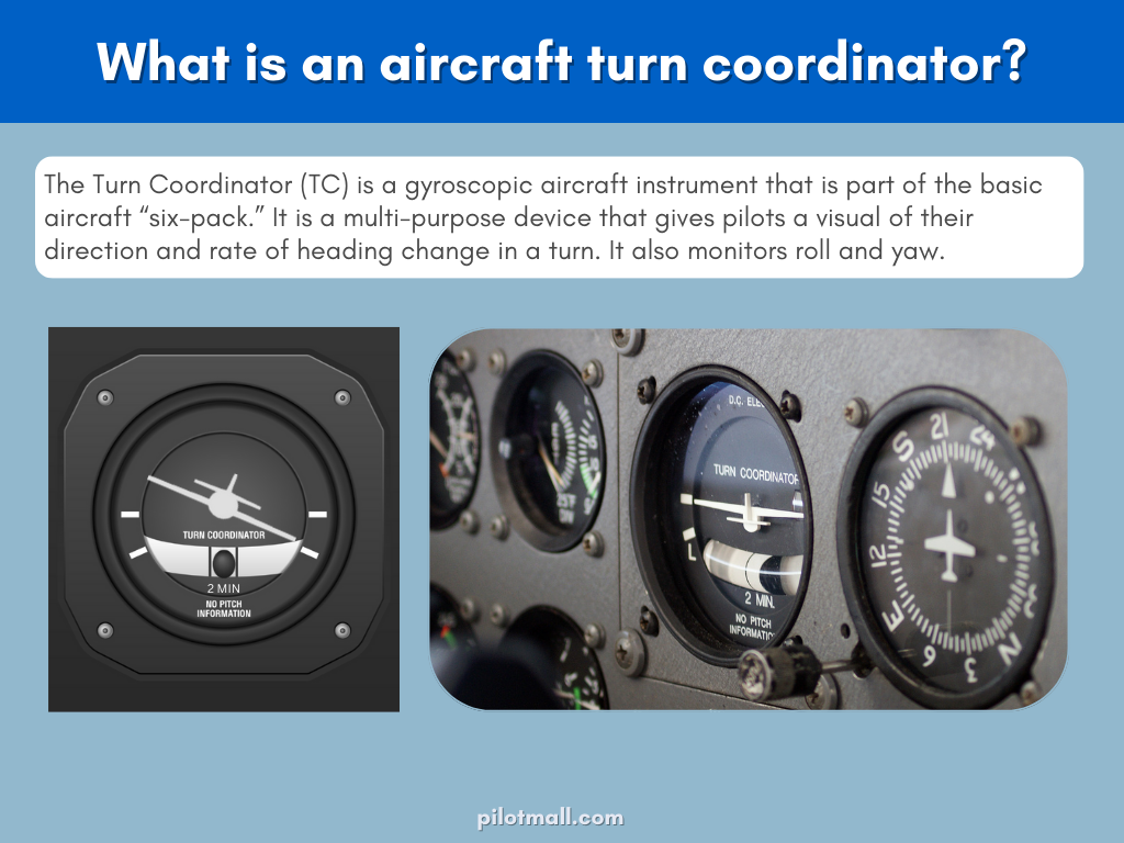
The Turn Coordinator (TC) is a gyroscopic aircraft instrument that is part of the basic aircraft “six-pack.” It is a multi-purpose device that gives pilots a visual of their direction and rate of heading change in a turn. It also monitors roll and yaw.
What does a turn coordinator do in aircraft?
The turn coordinator is essentially two instruments in one. The top part of the instrument gauge is the turn indicator which looks like a little plane silhouette. When you enter a turn, the wings of the little plane icon dip correspondingly to show the direction and rate of turn.
The bottom part of the turn coordinator gauge is a simple ball-and-fluid inclinometer with the “black ball” resting in the center. Its purpose is to measure any yaw in the turn.
During a coordinated turn, the black ball should remain in the center of the gauge(which is coordinated flight). If the ball drifts left or right, you are in a skidding or slipping turn (more on what that means and how to correct it later).
How does a turn coordinator work?
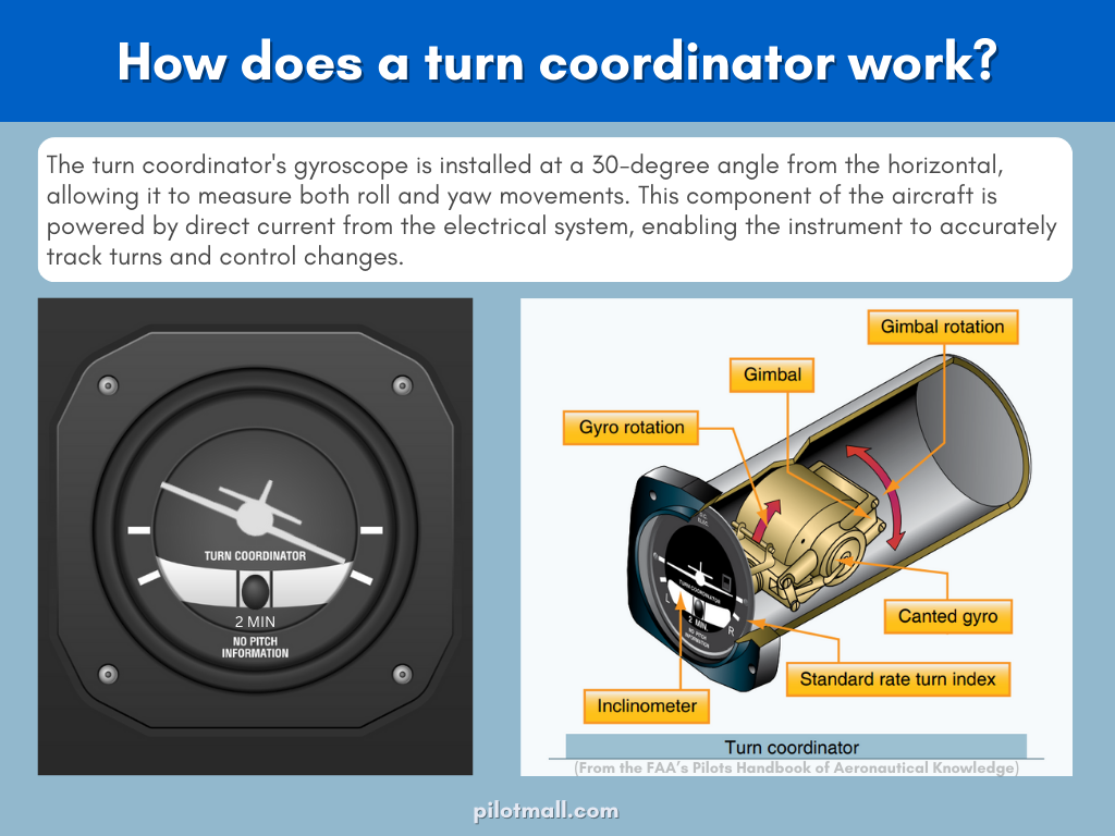
The standard turn coordinator works using a gyroscope, like the attitude indicator (AI) and heading indicator (HI). The difference is that the gyros on the AI and HI usually work with suction from a vacuum pump. The turn coordinator’s gyro, on the other hand, works using direct current from your aircraft’s electrical system.
The turn coordinator’s gyro spins at about 10,000-15,000 revolutions per minute (RPMs). At this speed, the gyro will feel rigid and remain in one place. Here is where gyroscopic precession comes into play.
You may remember that gyroscopic precession is the movement of the gyro in response to forces acting upon it. When force is applied to a spinning gyro, the resultant force will be 90 degrees in the direction of rotation.
With this value constant and known, the gyro in a turn coordinator is mounted behind the dial on a 30-to-45-degree angle upward from the long axis of the aircraft.
As you enter a banking turn, the force caused by the turn is translated to the gyro and registers on the turn coordinator gauge. You get feedback on both your initial roll rate and your stabilized rate of turn.
Glass cockpit turn coordinators:
If you’re flying a glass cockpit, your turn coordinator’s components are a little different than a gyro coordinator, but you’ll still use it the same way. Glass cockpit turn coordinators rely on the Attitude and Heading Reference System (AHRS) rather than a gyro to get their readings.
Quick Tips: The turn indicator and slip skid indicator gauges are combined with other instruments on your cockpit screen. Look for the turn indicator at the top of your horizontal situation indicator (HSI).
The slip and skid indicator can be found below the roll pointer. Instead of the small physical ball of an inclinometer, you’ll see a small horizontal line that floats left and right during an uncoordinated turn just like a ball would.
What is the difference between a turn indicator and a turn coordinator?
With similar names and functions, it’s easy to confuse the difference between these two instruments. The key difference between a turn indicator and turn coordinator is that while both show the rate of heading change, the turn coordinator also provides feedback on the rate of roll. This additional data is possible because the gyros of a TI and TC are mounted differently.
- The Turn Coordinator
The TC gyro is mounted with the front of the gyro at a 30-to-45-degree angle higher than the rear. This angle lets the gyro sense rotation not only around the vertical axis but also the longitudinal. That means the turn coordinator will show you both the rate of heading change and the rate of roll.
- The Turn and Slip Indicator
A Turn and Slip Indicator (TI) has a simpler design than the turn coordinator. A TI gyro is mounted in line with the long axis of the aircraft. This, when used correctly will indicate that you are in a standard rate turn of 3 degrees per second.
The TI will still work in unusual attitudes accurately measuring the rate of heading change. However, it will not be reliable for indicating both bank angle and the roll rate of the aircraft.
If you want more detail on how both TCs and TIs work, plus the differences between them, check out this turn coordinator video from Aviation Theory.

How to use a turn coordinator
So, now that you know what a TC is, how it works, and what makes it different from a turn indicator, you may be wondering, “how do I actually use this darn thing?”
Standard Rate of Turn
During VFR flight, the turn coordinator is used to help you execute smooth banking turns at standardized rates. When the wing of the silhouette plane on the gauge dips down to align with the bezel hash mark, that lets you know you are making a standard rate turn.
If your miniature plane’s wing stays above the standard rate hash, your turn is less than the standard rate. If the wingtip drops below the hash, you’re turning faster than standard.
A standard rate turn is defined as a 3 degrees per second turn. If you hold your aircraft in a standard rate turn, it will take one minute to make a 180-degree turn and two minutes for a 360-degree turn.
Why is a standard rate of turn important? For one thing, knowing how to execute a standard rate turn means you’re prepared to fly a reverse course if your VFR flight unexpectedly encounters IFR conditions. All you need to do is perform a 1-minute coordinated turn which will turn your aircraft 180 degrees and out of IFR weather.
The Standard Rate Turn Memory Aid:
-
3 degrees per second
-
One minute to make a 180-degree turn
-
Two minutes for a 360-degree turn
Standard rate turns also help air traffic controllers. Even in VFR flight, standard rate turns are used in holding patterns and approaches. The controller who is routing and managing IFR traffic will expect slower moving General Aviation (GA) aircraft to change their headings at standard rates of turn.
Avoid/Correct Slips and Skids
Now let’s talk about using the inclinometer portion of the coordinator.
Ideally you will keep the floating inclinometer ball between the two vertical lines of the tube gauge throughout your smooth banking turns.
If you are skidding through your turn, the ball will be forced outside the vertical lines, that is, centrifugal force will act on it more so than gravity causing the ball to skid outside of the markers.
If you are slipping through the turn, gravity will affect the ball more so than centrifugal force. This will cause the ball to “fall” toward the inside of the turn.
If the ball starts to drift outside the vertical lines in either direction, your instructor may tell you to “step on the ball”. This means you should apply rudder to the side that the ball is on in order to re-center the ball and move back into a coordinated turn.
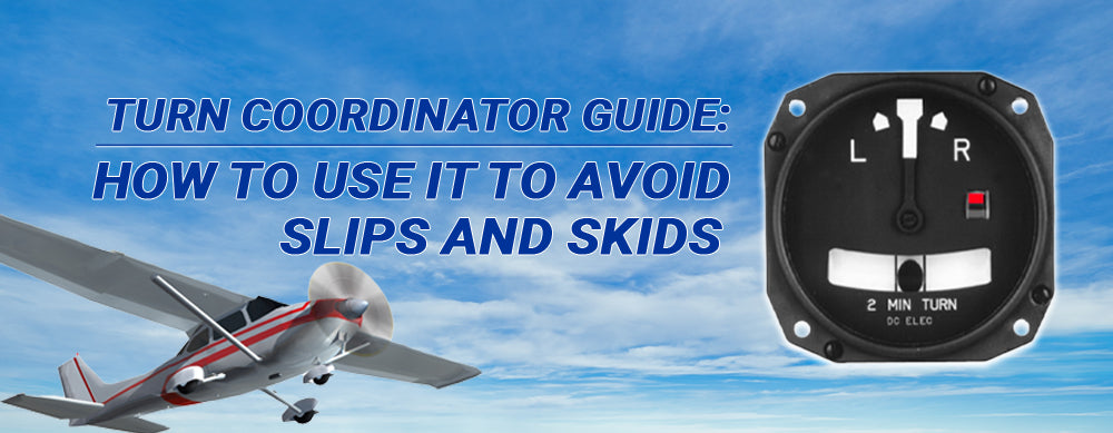
Want to learn more? Our in-depth slip and skid guide delves into more details on each of these uncoordinated turns. We also cover why a skid turn is dangerous plus share situations when a slip turn can actually be useful.
Keep the learning going with more aviation guides:





1 comment
Thomas
Hi there!
I was looking to further understand how the 30 degree mounting of the turn coordinator allows for sensing in two axes. Does the offset require a secondary sensing tool as the gimbals continue to only provide a single degree of freedom?
Thanks in advance!